Publications IPH Magazine Revista IPH Nº17 A study on hospital infection control through architecture in 1980: Chapecó Regional Hospital case study
- IPH Magazine #17
- COVID-19 pandemic and the trends in healthcare design: insights from the "Decalogue for Resilient Hospitals"
- Healthcare closer to people: A qualitative study of a Swedish reform on healthcare delivery
- Spatial flexibility and extensibility in hospitals designed by João Filgueiras Lima
- Design Insights from a Research Initiative on Ambulatory Surgery Operating Rooms in the U.S.
- A study on the development of the concept growth and change on hospital architecture in Japan
- A study on hospital infection control through architecture in 1980: Chapecó Regional Hospital case study
- Natural ventilation for hospitalization environments: historical aspects
- Hospital architecture and its propositions for beginners and experts
A study on hospital infection control through architecture in 1980: Chapecó Regional Hospital case study
Chayane Galvão and Jonathas Magalhães Pereira da Silva - PUC Campinas, Brazil
ABSTRACT
This article is part of a master's research that seeks to investigate architectural developments in healthcare spaces through social, technological, and legislative influences. Part of the work presented here seeks to exemplify and illustrate by means of a case study of how Infectious-Predictive Architecture appeared in Brazil between 1974 and 1994. The Hospital Regional de Chapecó (Santa Catarina), designed by Irineu Breitman in 1980, is analyzed with markings and re-reading of the design plans and points out the design strategies applied in the built environment in order to contain the spread of diseases. The time frame is due to the fact that federal legislative changes have occurred in the period driven by technical support that questioned and transformed the existing paradigms. Through the study, the solutions applied in each situation are questioned, and it is not always possible to understand the design techniques used.
Keywords: hospital architecture, infection control design, architectural design.
A study on hospital infection control through architecture in 1980: Chapecó Regional Hospital case study
Since the emergence of hospitals, numerous changes have occurred due to different factors from several areas of knowledge. Throughout history, the healthcare setting has improved significantly, consequently changing the hospital architectural space. These changes occurred due to new medical principles and procedures, as well as technological innovations, mainly in the health and construction areas. But it is only from the middle of the twentieth century that the beginning of the formulation of Brazilian regulations related to the formation of these environments can be observed.
These regulations arose from the need to generate a minimum standardization in some environments of the hospital so that it could offer the best ergonomics and flow to patients and clinical staff. They reflected the "good practices" gradually built and listed, in addition to the medical knowledge of each period.
Among these reflections seen in hospital regulations in Brazil, we highlight here the Construction and Installation Regulation for the General Hospital, issued by the Federal Government in 1974 and that brought to the legal records the concern about the control of
nosocomial infections.
Throughout the 20th century there were several important moments in the change of paradigms regarding the control of contagion and hospital infections. For example, in the 1970's the regulation suggested professionals should: "Avoid crossing clean and contaminated traffic" (BRASIL, 1974, p.5). This recommendation referred to the use of corridors known as "dirty and clean", which controlled, for example, the entry of clean clothes in the environment and the exit of waste by another path. This is how the sectors containing operating rooms and nurse stations used to be designed. In the 1970's, it used to be strongly recommended for the project to have two circulation corridors, which increased the circulation areas in any hospital plant.
In 1994, the new federal legislative regulation is released addressing healthcare facility physical designs already considering the common knowledge that contagion issues could be controlled with proper hygiene, through asepsis. Such a knowledge emerged in 1980 when the so-called Infection Control Design (BRAZIL, 1995) started to be employed along with medical procedures in the search for the improvement of cure and prevention of nosocomial infections.
The Infection Control Design aimed at achieving safer hospitals, often without a thorough scientific basis. Infection Control Design was the name given to actions imposed by 1974 regulations, such as septic operating rooms, surgical ward with double aisle, private elevators and freight elevators to transport "dirty" waste, i.e. potentially infectious waste, among others.
In 1980 the consolidation of hospital infection prevention is reformulated. From this point on, through worldwide publications, the understanding of Infection Control Design begins to change. Official documents used to refer to previous practices as "useless magical rituals that only increase hospital costs" and that would be revealed by the new regulation based on technical and scientific findings (BRAZIL,
1995, p.15).
It was in the 1980s that the Universal Precautions, Safety Procedures, and the adoption of Individual Barriers (gloves, apron, mask, and safety goggles) became part of employees and the general public routine within healthcare facilities. By understanding and comprehending individual safety actions in these spaces, hospital architecture becomes collaborative - and no longer decisive - providing the environment accurately for these actions to happen:
Based on this, the present article presents an analysis of Chapecó Regional Hospital based on remarks and re-reading of the architectural project, as well as supported by beliefs and legislation in force at the time for the best understanding. The choice of this architecture, signed by Irineu Breitman, is justified by the date it was conceived, i.e. 1980. It was a hospital project legally oriented by the restricted regulations of 1974 and executed in a moment of changing knowledge regarding infection control hospital design architecture.(... ) a sink, per room, undoubtedly constitutes a solid support to the implantation of the new tendency of care; as well as: water tap, activated by foot command or by other means, able to free the hands and preserve them from contamination; and, also, the provision of space under the sink for the placement of a plastic bag-holder for dirty clothes, a plastic bag-holder for solid residues and a solid container for the safe collection of used injection needles and other sharps, complete the required support: Raised shelves, above the sink, for the storage and ready-use, always at hand, of the "individual barriers" (gloves, mask, apron and others). Elevators and freight elevators are the usual means of transporting clothing; when bagged and packed in closed cars, they do not require additional precautions or safety; the recommendation that transportation be done by elevators, preferably destined for services, or that do not carry patients at the same time, are dictated only for reasons of "humanization" and discipline (BRAZIL, 1995, p.32).
The material used here is part of a broader research, where a new case study is added later, representing the architectural thinking after the 1994 regulation. Our purpose at this point is to illustrate and understand how this knowledge and regulations were translated into the hospital architectural space, considering its peculiarities.
Chapecó Regional Hospital
Irineu Breitman was the architect responsible for designing this project being presented and studied here. He also founded, in 1970, HOSPLAN, later renamed to HOSPITASA, which was the office responsible for the project of Chapecó Regional Hospital. The team, besides Irineu, was composed by two other architects and a consulting physician. Their projects presented very striking characteristics seen in other projects by Irineu: predominance of horizontal design as well as favoring natural ventilation and insolation (VICENTE, 2018).
Located in the city of Chapecó, in Santa Catarina state, the building of Chapecó Regional Hospital started in 1982, and in 1986 it was open to the public with 60 beds available. Currently it is known as Western Regional Hospital. As verified in the analysis of the architectural technical drawings in Irineu Breitman's design, the original 1980's design had six main floors, occupying an area of approximately 35 thousand
square meters.
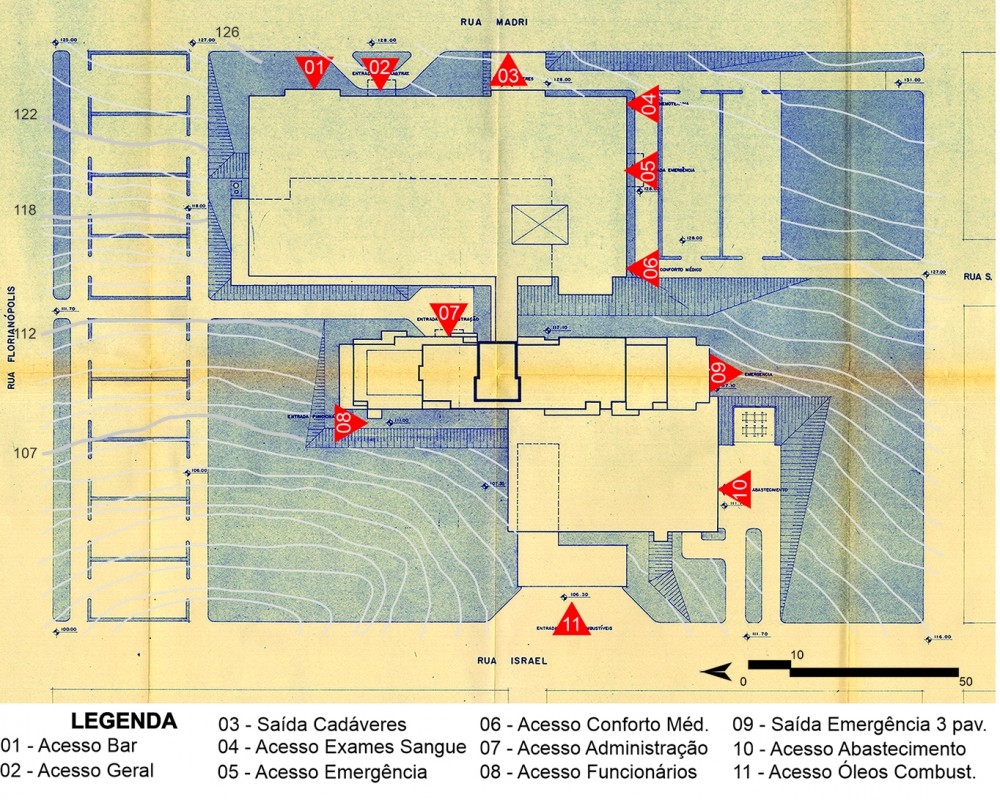
The site had 15% inclination in the east-west axis. To obtain six floors, Breitman used 5 plateaus - at elevations 126, 122, 118, 112 and 107 (Illustration 1), therefore naming his design vertical-staggered, connecting the floors through a rigid core (elevators and stairs), allowing direct access to each area.
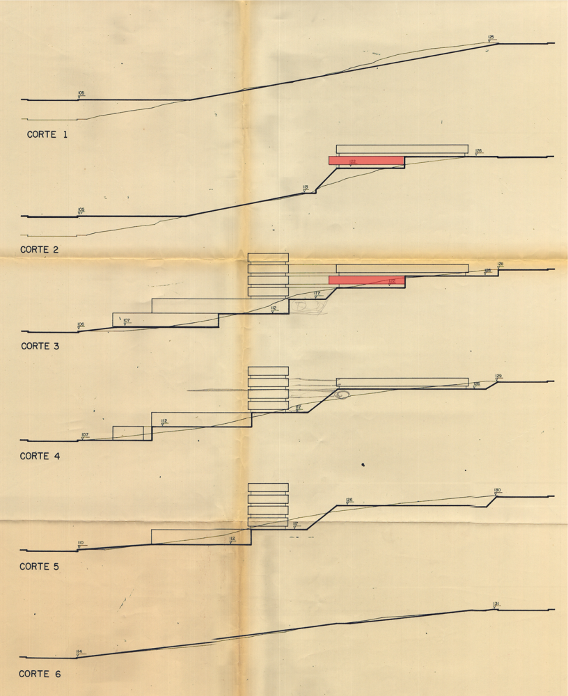
In Illustration 2 it is possible to see the cuts made in the site and each floor setting. Through sections 2 and 3 it can be observed that the east wing of the fourth floor is partially buried. Breitman justifies his choice: "The need to provide most of these services with air conditioning was explored by placing them on floors with less possibility of lighting and ventilation", a reference to surgical and intensive care services, as will be shown in the individual floor study.
On the first floor were placed boiler and air conditioning centers. It has direct access from Israel Street, and it is supported by the plateau at elevation 107. It also offers direct access for vehicles into the garage and individual accesses into other rooms. In a statement collected for his dissertation research, Lucio Breitman - Irineu's son - pointed out that the difficulty imposed by the high inclination of the terrain made possible the implementation of underground galleries below the first floor, which allowed an easier and faster access to and maintenance
of other floors.
Illustration 1 - Chapecó Regional Hospital Implementation
Source: IPH Collection, 1980. Adapted by the author.
Illustration 2 - Schematic cuts of plateaus included in the site, emphasis on the 4th floor
Source: IPH Collection, 1980. Adapted by the author.
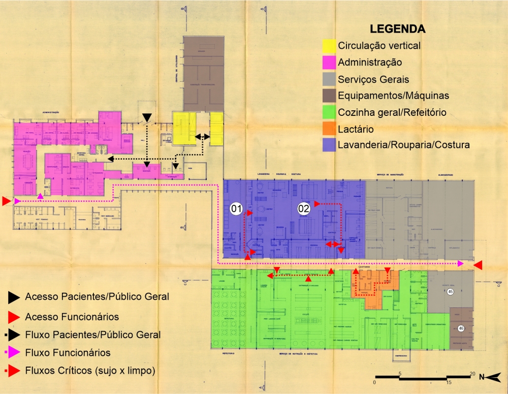
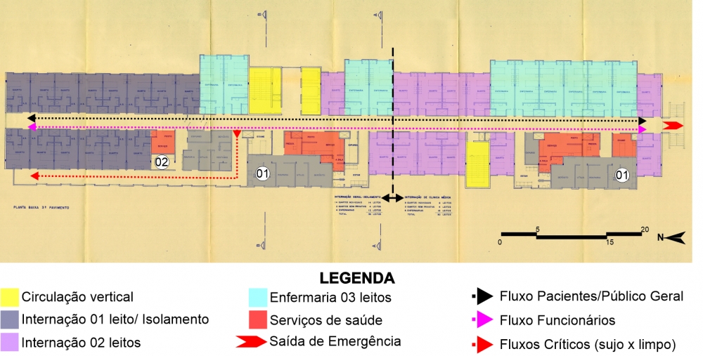
The second floor (Illustration 3) is served with an employee access on the north façade, a service access on the south façade, and a third access for the general public located on the east façade. The left block shelters general administrative services and a hospitalization area. The connection with the rest of the floors is through this same block by an enclosed stairway and three elevators. The flows are set apart by the location of the accesses and the distribution of the internal environments, which create a barrier and guide the public.
Illustration 3 - Chapecó Regional Hospital: 2nd floor
Source: IPH Collection, 1980. Adapted by the author.
The block on the right is served with laundry, kitchen, lactation room, maintenance room, and storeroom services. This block reflects the main beliefs of the time through its architectural design.
Although already equipped with some technological advances and knowledge regarding medical processes, hospitals in the 1980s still hold the architectural solutions accountable for the prevention of infections. These solutions played the role of building maintenance. The term used by Karman (2011) years later refers to the action of anticipating and executing an architecture that prevents and anticipates the facts so feared at the time.
An example of this belief in Brazil appears in 1972 with Jarbas Karman when he defines the laundry as "a central station that receives and distributes germs." (KARMAN, 1972, p.59). In 1976 the American Hospital Association publishes the third edition of Hospital Infection Control, and regarding the laundry room it is stated, "In addition to the room for sorting and storing, the laundry room must have separate rooms for processing, stocking clean linen, and sewing for sanitary facilities, and for an office." (AMERICAN, HOSPITAL ASSOCIATION, 1976, p.59).
We highlighted the flow cited by the American Hospital Association in Illustration 3, which happens through the access, followed by dirty clothes carts passing through a contact-free and isolated room. Between separation and the completion of washing there are no direct exchanges between physical agents, only through the double door washing machines.
The room dedicated to the last phase of washing includes a control antechamber, centrifuges, dryers, calender, presses, ironing, and a new control room. The flow happens from left to right, and before reaching the linen room for new distribution it also passes through the sewing area. This flow and distribution make up the barrier system, delimiting the contaminated and disinfected areas (numbers 1 and 2, respectively) (BRAZIL, 1995).
In the lactation room and in the kitchen the idea of a barrier system is repeated. There is an area to welcome "contaminated" carts, which furthers the distribution of dirty dishes to another environment and carries out the exit for distribution through another access, the "clean" one. Karman (2011) described the rooms making up the kitchen area through the barrier system that was already a reality in 1980:
Under the aspect of physical planning, the conventional system contemplates the following environments and components, subject to minor variations: loading and unloading platform; reception and inspection area for food and utensils; storage area; cold storage area; nutritionist room; restrooms; cleaning material storage; waste collection room; food preparation areas; cooking areas; diet preparation area for breakfast and snacks; area for distribution; area for washing dishes, cutlery and trays; area for washing and storing pans; area for washing carts; cafeterias, snack bar for the public, and snack bar for blood donors; lactation room; room for enteral nutrition (KARMAN, 2011, p. 352 ).
The third floor (Illustration 4), the first within the hospitalization tower, represents the smallest area. It houses general hospitalization and isolation, which gives raise to some questions concerning the barriers used in the project. The arrows in the illustration delimit the general hospitalization-isolation area to the left and the clinical hospitalization area to the right.
Illustration 4 - Chapecó Regional Hospital: 3rd floor
Source: IPH Collection, 1980. Adapted by the author.
The general admission-isolation area is comprised of four nursing wards with three beds each and two semi-private rooms, two beds each. This area is served by the central nursing station, exam room, prescription room, and dirty and clean pantry (number 1). It is interesting to note that the same service occurs in the clinical hospitalization area, but it is not repeated in isolation: the 14 isolation rooms - one bed each, are served only by a smaller size station and one pantry (number 2), with no separation between dirty and clean areas.
Mezomo (197?), in the 70's, exemplified three types of meal distribution systems found in hospitals: decentralized, centralized, and mixed systems. The decentralized was basically preparing the meal in the kitchen followed up by distribution in thermal carts with the support of extra pantries located in each admission unit to separate the portions and identify the trays. The centralized system did not use pantries, preparing, storing, and packing the meals inside the kitchen, leaving only for direct distribution to the rooms. The mixed system is defined as:
It can be the system, for example, where the meals come portioned and identified from the kitchen, and the assembly of the trays is done in the pantry itself. Or then, decentralized distribution for patients with general diet and centralized distribution for patients with special diets, allowing greater supervision in the latter. Another modality would be the centralized distribution of cold food and decentralized distribution of hot food (MEZOMO, 197?, p. 112).
The excerpt we highlighted may explain the irregular use of dirty and clean pantries present in the project. For example, on the third floor there are dirty and clean pantries to serve the rooms and wards, but only one pantry - without definition - to serve the isolation rooms. This could be justified by thinking that the food for patients in isolation leaves the kitchen and goes straight to the rooms, without going through a finishing process or storage in the clean pantry. The pantry intended to serve this ward should provide a support, if necessary, or just receive
dirty dishes.
The same will be observed on the sixth floor, where the children's ward is composed only of one pantry, with no definitions. Mezomo (197?) emphasizes the importance of carefully preparing and transporting baby bottles, stressing that the handling of baby bottles should be kept to a minimum. Through the design analysis carried out here it is understood that Irineu applied to Chapecó Regional Hospital the mixed system. This information was exposed here in order to somehow answer the questioning about the design solutions employed.
There is another question concerning the access to isolated patients, since there is a transfer area in the main corridor and another access through a second corridor. These secondary entrances to the isolation rooms only happen on one side of the floor, leaving six rooms without windows. Still, it does not present any physical barrier, which could indicate a passage allowed only to authorized people. The drawing allows us to understand that this corridor creates two accesses to the rooms. There is an antechamber serving these isolation rooms, which according to the American Hospital Association would rule out the use of extra corridors:
3) an anteroom with sink, cabinets for clean aprons and other materials, and space for a container of dirty materials. This anteroom facilitates the implementation of isolation techniques without the need to use the hallway. Illustration 5 shows a floor plan of an isolation room with an anteroom (AMERICAN HOSPITAL ASSOCIATION, 1976, p. 79).
The third floor is also the only one with an emergency exit, located on the south façade with direct access to the outside area. Regarding the escape routes and emergency exits, the "Fire Prevention Standards and Specifications", published in 1979 by the Santa Catarina Military Fire Department specified:
Article 141 - The number of Enclosed Stairs in buildings for other uses will be calculated according to the following conditions:
(a) Buildings taller than 30 (thirty) meters must be provided with 2 (two) staircases.
(b) The floor area for a single Enclosed Staircase cannot be greater than 500 (five hundred) m2.
(c) The maximum distance between the furthest point and the entrance door of the antechamber will be 35 (thirty-five) meters, measured within the perimeter of the building; (SANTA CATARINA, 1979).
Still regarding the third floor - where begins the hospitalization tower - it is noteworthy what Lucio Breitman highlighted as the importance given by Breitman concerning "form and function" of the structure. The 1.20 x 1.20 m grid throughout the design is applied even to the dimensioning of the rooms and the number of beds. The architect used to employ 1 grid or half a grid, depending on the number of patients to be housed in the room. The three-bed nursing wards are approximately 8.40 meters long, while the two-bed rooms are 6 meters long. His rigid way of following the stipulated values in his grids allowed a total use of the space, without waste or over dimensioning of the apartments, providing the façade of the hospitalization tower with a very interesting game of volumes and rhythm. The suggestion of adopting this grid dimension would be addressed years later by the RDC regulation published in 2002.
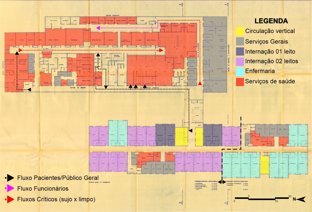
The fourth floor (Illustration 5) is where we can see the building extension towards Madri Street, currently Montevidéu Street (east façade). In this floor there is another hospitalization tower for Gynecology and Obstetrics Hospitalization, with 30 beds, and Obstetrics Hospitalization with Rooming In, with 42 beds. Besides the hospitalization tower, the is served by surgical and obstetrics center, nursery, recovery and intensive care area and sterilized material center.
The transition from one ward to the next is connected through a living room, which is seen as a waiting area for those accompanying patients in surgery. Although justified, the location of this area can be invasive, since accessing the surgical center requires patients and medical staff to walk through freely without physical barriers.
Illustration 5 - Chapecó Regional Hospital: 4th floor
Source: IPH Collection, 1980. Adapted by the author.
The main flow happens through the "dirty" floor, which contemplates the passing through of women in labor, surgical patients, and patients in need of intensive care. The patient access into the surgical corridor happens through two transference areas. When there is no need of ICU transfer the flow from labor room and operation room is straight to recovery rooms. Every access and exit are supported by a transference area. Karman describes such areas as separation spots between one flow and the next:
4. Transference room: The bed or stretcher on which the patient is brought from his room houses and collects considerable amounts of bacteria that cannot penetrate the operating rooms. It is necessary, therefore, that in the transfer room, located at the entrance of the surgical (and obstetrics) set, the clean patient is transferred from his bed to a disinfected stretcher, totally clean and treated with lint fixers (KARMAN, 1972).
To organize the obstetrics center process there is an access through preparation and labor rooms. While the mothers are transferred to the recovery room, the babies are taken to one of the four nurseries available in the hospital: observation, infected, pathologic, and free from pathogenies. The nursery for babies without pathogenies opens a window to the corridor for patients, so relatives and visitors may see them.
The medical flow occurs through the corridor on the right and leads straight to preparatory rooms for surgery. To carry out infectious surgery there is a preparation room specific for the medical team. The "clean" corridor exclusive for doctors and nurses leads to the second access to operation rooms.
Since 1995 the Ministry of Health broadly publicizes that operation rooms must be located between two corridors: "it does not at all contribute to the asepsis improvement of the block; on the contrary, it can mean a hazard to it if another access is introduced; it is a design solution operationally expensive and that lacks technical justification" (BRASIL, 1995, p.57). The contact between medical staff and patient for hours inside the same space and the "sending off" of patients along the same path as dirty materials and clothes does not invalidate the cleanness of the corridor they go through, as long as the waste is properly packed. (BRASIL, 1995).
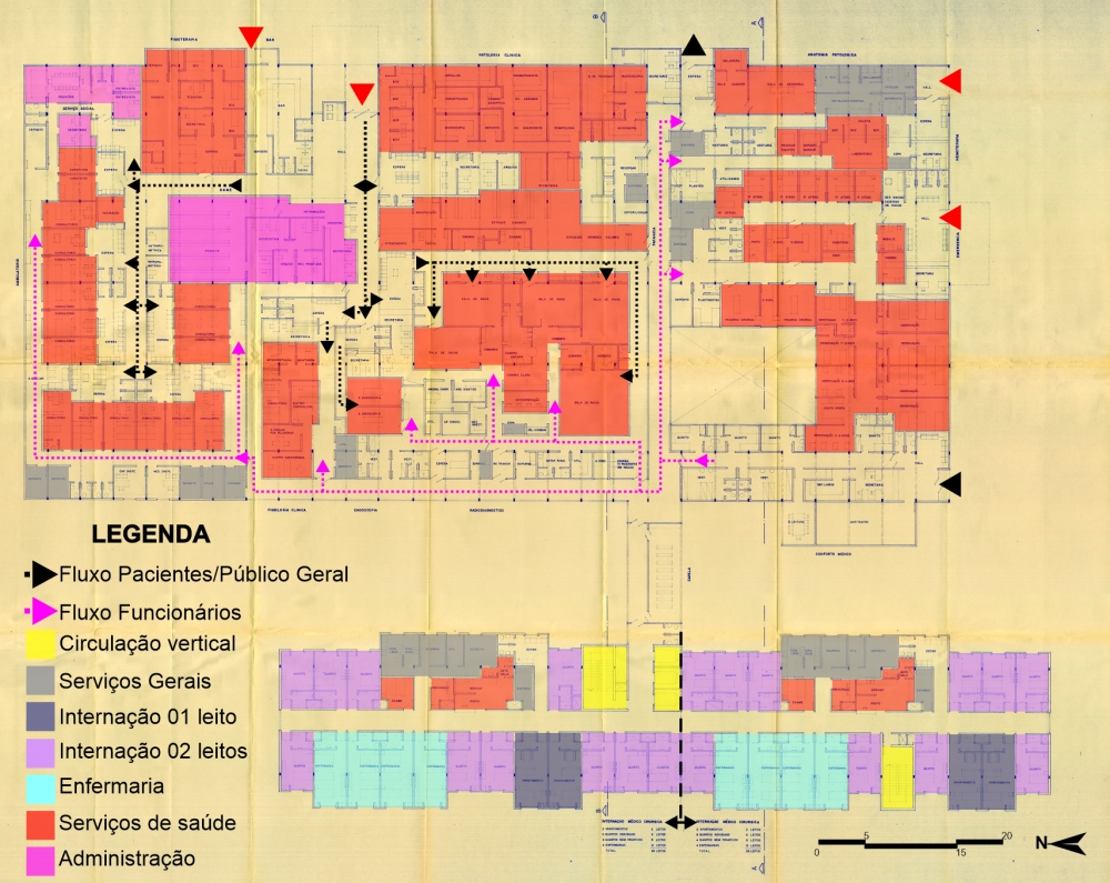
The fifth and largest floor (Illustration 6) is served with consultation space, physiotherapy, exams, laboratory, pathology, emergency service and medical comfort, in addition to medical surgical hospitalization sector. The hospitalization tower block on this floor offers 68 beds divided between wards, rooms, and private apartments. The connection to the second block is made through the chapel.
This is the last floor that makes direct contact with the street, which in addition to the greater extension and grouping of services enabled the location of several accesses. The three accesses on the east façade are for catering, general entrance for exams and consultations, and access/exit to the morgue (from left to right). The three other accesses, located on the south façade, lead to blood center, emergency and medical comfort (from top to bottom).
The general entrance splits the flow into three options: consultations, physiotherapy, and social work; clinical pathology area; or even exam rooms. The fifth-floor plan organizes flows as on the second floor: distributing environments.
Illustration 6 - Chapecó Regional Hospital: 5th floor
Source: IPH Collection, 1980. Adapted by the author.
Every flow leading to a doctor's office comes to a waiting room, therefore there are two accesses to the consultation room. The doctor enters through the corridor coming straight from the comfort area. In addition to the offices, all exam rooms have separate entrances, apart from electros since they are performed by technicians.
The patient access to the emergency service is carried out only through the south façade, and the access for the medical team takes place through the long corridor that divides the exam and emergency areas. There is also a void in this area, which could be used to install windows and enable natural ventilation in the medical staff rooms.
The sixth floor, followed by the engine room, wraps up the tower block. There (Illustration 7) we find the pediatric hospitalization unit, which is subdivided into subunit A and subunit B. Subunit A, on the left side, has four wards dedicated to children between 0 and 2, with six beds each. These wards are monitored by two nursing stations. There are also three private rooms, to kids between 0 to 2, with accommodation for a companion. Subunit B contains wards for children between 2 and 7 years old; wards for kids from 7 to 12; and semi-private rooms for ages 7 to 12. Each ward serving children between 2 and 7 counts on an individual nursing station, and the others are commanded by a central station.
On this floor the pantry is a single space, with no division between dirty and clean areas. In addition to this uncertainty about the spaces, it is questioned why there is no room for patients aged 2 to 7. There is also a recreation area and outdoor area on the floor, also characterized as an emergency exit.
As for insolation and ventilation solutions applied to the project, Breitman says: "The placement of hospitalization units, with patient rooms facing east and west, will enable adequate insolation." It is known that, when designing, the western sun is usually avoided, blocked, or controlled through different strategies. The weather in Chapecó is cold, which may justify the west-facing spaces, so that the afternoon heat may remain in the environment during the night. However, no strategy was used to control, even if just specifically, this insolation.
In Illustrations 4, 5, 6 and 7, it is possible to observe variations in the positioning of hospitalization tower, however the protection from the west sun is null. The west façade contains many openings in this direction, again without any protection. The north façade, which is the most beneficial insolation according to some studies, is served with just a minimum number of openings. Lucio pointed out that insolation and adequate ventilation of environments have always been important considerations in all Breitman projects, and he believes that the option for the east-west orientation to the hospitalization tower is justified by the city cold climate.
Conclusions
When Chapecó Regional Hospital (CRH) was designed the vertical model was already widely accepted and replicated, including in Brazil. However, besides the personal characteristics and preferences of the leading architect - Irineu Breitman - the site did not favor a totally vertical project. I imagine that a single multi-story volume located in the center, or close to some of the surrounding roads, would hinder the development of the project, limit its access, and waste the large space available. Although its unevenness limitations, the scaling and distribution of sectors allowed all areas to be served and grouped as a typical 1980's layout would require.
CRH presents only a rigid core in the project without restriction of use to employees or companions. It should be considered, however, that although the project offers only one vertical flow option, its two largest floors - fourth and fifth - are composed of a horizontal plan, supported on plateaus, and not entirely overlapping, which makes it more difficult to include further options of vertical traffic. Budget issues should also
be considered.
When considering this deficiency in the supply of stairs or elevators, critical internal circulation must also be considered. As already pointed out, spaces such as kitchen, lactation room, laundry, sewing room and surgical center were classified as critical spaces, where the concern regarding nosocomial infection was constant. Considering placing another flow option could interfere with these critical intersections.
It is still possible to analyze the hospitalization towers with the ideas of Florence Nightingale and Tenon. Their studies applied to patients hospitalized in long pavilions with openings in both façades and a greater distance between beds were adapted in the 20th century and remain in current projects.
It can be said that a reinterpretation of their studies is applied to the hospitalization towers in the design studied here, as we see that the hospitalization floors are composed of long pavilions with openings on both sides, along which patients are accommodated. What changes is the separation by rooms and the decentralization of nursing stations.
However, for economic maintenance and efficient assistance
it is essential that rooms are arranged on both sides
of the corridors. Façades and corridors must be occupied only by patient accommodation.
It is always good to keep in mind that the most compact layout of beds
corresponds to the shortest service path (CYTRYNOWICZ, 2014).
The transfer areas within CRH surgical centers became obsolete after 1994, when the legislation no longer indicated the need to avoid crossing clean and dirty flows. These spaces used to be employed to exchange stretchers and keep the corridor "clean" and free from microorganisms likely to cause infections.
Finally, there are also individual rooms for anesthesiologists and chief nurses in the surgical centers. Although such spaces may not be essential to the functioning of this center it might be another way to compact the hospital building, for the exclusion of such spaces does not harm the flow or functioning of the surgical wing, on the contrary, makes it more compact and restricted to access only when necessary.
REFERENCES
AMERICAN HOSPITAL ASSOCIATION. Controle de infecções no hospital. São Paulo, SP: Sociedade Beneficente São Camilo, 1976. viii, 203 p.
BRASIL, Ministério da Saúde. Arquitetura na prevenção de
Infecção hospitalar. 1995. Available at: < http://www.anvisa.gov.br/servicosaude/manuais/infeccao.pdf > Access: 28/02/2020.
BRASIL. Ministério da Saúde. Secretaria de Assistência Médica. Coordenação de Assistência Médica e Hospitalar. Normas de Construção e instalação do Hospital Geral. 1974. Acervo IPH.
BREITMAN, Irineu. Projeto Arquitetônico Hospital Regional de Chapecó. 1980.
CYTRYNOWICZ, Monica Musatti, 1964 - Instituto de pesquisas hospitalares arquiteto Jarbas Karman - IPH: 60 anos de história / Monica Musatti Cytrynowicz. - 1. ed. - São Paulo: Narrativa Um, 2014. 176 p.
KARMAN, Jarbas. Iniciação à Arquitetura Hospitalar. IPH - Instituto de Pesquisas Hospitalares Arquiteto Jarbas KarmanSão Paulo - SP, Brasil - 1ª edição - 1972. Available at: < http://iph.org.br/acervo/livros/iniciacao-a-arquitetura-hospitalar-6 > Access: 16/3/2020.
KARMAN, Jarbas. Manutenção e segurança hospitalar preditivas / Jarbas Kannan ; (prefácio de Celso Skrabej. - São Paulo :Estação Liberdade; IPH, 2011. Available at: < http://www.iph.org.br/acervo/livros/manutencao-e-seguranca-hospitalar-preditivas-1036 > Access: 10/03/2020
MEZOMO, Iracema F. de Barros. Organização e administração do serviço de nutrição e dietética. [São Paulo, SP]: SBS, 197-]. 199 p.
SANTA CATARINA, Bombeiros Militares de Santa Catarina. Normas e Especificações Contra Incêndios, 1979.
VICENTE, E. R. S. A arquitetura de hospitais de Irineu Breitman. Revista IPH, São Paulo, n. 15, p.35-56, 2018.
Chayane Galvão is a master's degree student at POSURB-ARQ PUC-Campinas. Her research line is on Project, Innovation and Management in Architecture and Urban Planning. She is an Architect and Urban Planner from the State University of Santa Catarina (2013-2018). Her undergraduate thesis regarded the area of relationship between architecture, space, and feelings in hospital environments. She worked as Technical Drawing Monitor between 2014 and 2015.
chayanegalvao@hotmail.com
Jonathas Magalhaes Pereira da Silva is a PhD Prof. at POSURB-ARQ PUC-Campinas. As a consultant he worked in the technical coordination of: Social Space Planning of Rocinha RJ; 11 participatory plans in the mountain region of ES; urban planning projects for traffic corridors in SP; Master Plan for CDHU-SP, Sanitation Plan for Paragominas - PA; Infrastructure Plan for UNIFESP - São Paulo, among others.
jonathas.silva@puc-campinas.edu.br
Share


Send by e-mail: